
CAN Bus Signal Check
- Cable used
- Verification Instructions
- Oscillography of K-CAN, PT-CAN, F-CAN
- Resistance measurement order with matching resistance K-CAN, PT-CAN and F-CAN
- K-CAN
- PT-CAN, F-CAN
- Note!
- CAN bus not working
This manual is used to verify that the high level signal of the CAN and the low level of the CAN signal are correctly transmitted to the bus connection.
Cable used
Multifunction cable
Verification Instructions
- Voltage test (oscilloscope): To check the voltage, the battery must be connected and the ignition switched on.
- Resistance Measurement: When measuring resistance, it is necessary that the object to be measured is de-energized before measurement. To do this, the battery is disconnected. Wait 3 minutes for all capacitors in the system to discharge.
CAN information
The CAN bus (Controller Area Network) is a serial bus system with the following features:
- signal propagation occurs in both directions.
- Each message is received by all bus subscribers. Each bus subscriber decides whether he will use the message,
- Additional bus subscribers are added by simple parallel connection.
- The bus system forms a system with a driver. Each bus subscriber can be a driver or an actuator, depending on whether it is connected as a transmitter or receiver.
- A two-wire connection is used as a transmission medium. Wire designations: CAN low and CAN high.
- As a rule, each bus subscriber can communicate via bus with all other bus subscribers. Data exchange on the bus is governed by the rules of access. The main difference between the K-CAN data bus (body CAN bus), PT-CAN bus (engine and transmission CAN bus) and the F-CAN bus (chassis CAN bus) is:
- K-CAN: data transfer rate approx. 100 Kbps Single wire possible.
- PT-CAN: data transfer rate approx. 500 Kbps Single wire mode is not possible.
- F-CAN: data transfer rate approx. 500 Kbps Single wire mode is not possible.
Driver: The driver is an active communication partner from which the communication initiative originates. The driver takes precedence and controls the communication. It can send messages to the passive bus subscriber (actuator) via the bus system and, upon request, receive its messages.
Actuator: the actuator is a passive communication member. It receives a command to receive and transmit data.
System with master device: in a system with a master device, communication participants may at a certain point in time assume the role of master or actuator.
Oscillography of K-CAN, PT-CAN, F-CAN
For greater clarity, whether the CAN bus works flawlessly, you need to watch the bus communication. At the same time there is no need to analyze individual bits, and you just need to make sure that the CAN bus is working. Oscillography shows: “The CAN bus obviously works without disturbances”.
When measuring with a voltage oscilloscope, a CAN (or high CAN-High) low-level wire and ground receive a square wave signal within the voltage range:
K-CAN:
Low CAN level relative to mass: U min = 1 V and U max = 5 V
High CAN level relative to mass: U min = 0 V and U max = 4 V
These values are approximate and may vary, depending on the bus load, by up to 100 mV.
Oscilloscope settings for measurement on the K-CAN:
CH1: Probe 1, Rank 2 B / div; DC DC2 connection: Probe 2, Grade 2 V / div; DC connection Time: 50 ms / div
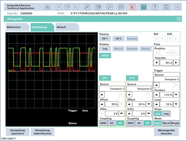
Fig. 1: K-CAN measurement: CH1 low CAN level, CH2 high CAN level
When measuring with a voltage oscilloscope, a CAN (or high CAN-High) low-level wire and ground receive a square wave signal within the voltage range:
PT-CAN and F-CAN
Low CAN level relative to mass: U min = 1.5 V and U max = 2.5 V
High CAN level relative to mass: U min = 2.5 V and U max = 3.5 V
These values are approximate and may vary, depending on the bus load, by up to 100 mV.
Oscilloscope settings for PT-CAN (or F-CAN) measurement:
CH1: Probe 1, Rank 1 B / div; DC DC2 connection: Probe 2, Grade 1 V / div; DC connection Time: 10 ms / div 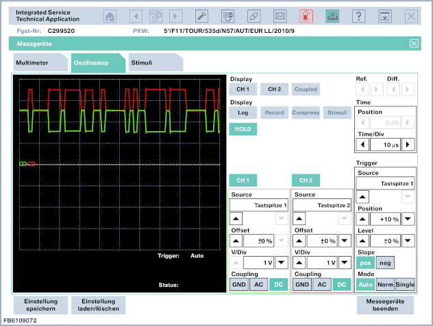
Figure 2: PT-CAN Measurement: CH1 Low CAN, CH2 High CAN
Resistance measurement order with matching resistance K-CAN, PT-CAN and F-CAN
The process of checking the resistance measurement:
- CAN bus must be de-energized
- No other measuring devices should be connected (parallel connection of measuring devices)
- Measurement takes place between CAN low level and CAN high level wires.
- Actual values may differ from specified values by several ohms.
K-CAN
A separate resistance measurement cannot be made on the K-CAN bus, since the resistance varies depending on the switching logic of the computer!
PT-CAN, F-CAN
To prevent the reflection of the signal, two CAN bus subscribers (with the maximum distance in the PT-CAN network) are loaded with a resistance of 120 Ohm. Both load resistances are connected in parallel and form an equivalent resistance of 60 ohms. With the supply voltage disconnected, this equivalent resistance can be measured between the data lines. In addition, individual resistances can be measured individually.
Measuring instructions with a resistance of 60 ohms: Disconnect a readily accessible computer from the tire. Measure the resistance at the connector between the low and high CAN wires.
Note!
Not all cars have a terminating resistance on the CAN bus. The presence of the built-in terminating resistance on the connected vehicle can be checked using the appropriate wiring diagram.
CAN bus not working
If the K-CAN or PT-CAN data bus is not working, then there may be a short circuit or a broken high or low CAN wire. Or faulty ECU.
To localize the cause of the fault, it is recommended to proceed as follows:
- Disconnect the CAN bus subscribers in turn until a block is found that is the cause of the malfunction (= ECU X).
- Check cables to computer X for short circuit or open circuit.
- If possible, check the ECU X.
- Such a sequence of actions leads to success only if the short circuit has a verifiable wire from the computer to the CAN bus. If the wire in the CAN bus itself has a short circuit, then you need to check the wiring harness.
We reserve the right to typographical errors, semantic errors and technical changes.